Setting up a Drum Kit
Supplies
-
A microcontroller
-
The Pi Pico is recommended, but click below to see information about other microcontrollers.
Microcontroller information
- Pi Pico
- This micro controller was created by the Raspberry Pi foundation, so it means that buying one supports them instead of random companies cloning Arduinos. They are considerably more powerful than any of the other supported Arduinos. The Pi Pico supports a few extra features, such as USB Input (which allows for XB1 / Series compatability), Peripheral microcontrollers and the GHWT tap bar. Note that the Pi Pico runs at 3.3v, so it can just be used as is for PS2 and Wii adapters. Pi Picos also tend to be quite cheap and often have the advantage that they can often be brought at local stores. With the currrent firmware, picos work much much better than arduinos if your goal is to create adaptors, but they also work better for direct wiring too. There are many boards based on the Pi Pico as well, and all of these work just fine with the firmware.
- Sparkfun Pro Micro (5v)
- The 5V Pro Micro will work okay for direct wiring, but being that it runs at 5V, it will require voltage conversion to build Wii adapters and PS2 adapters and turntables.
- Sparkfun Pro Micro (3.3v)
- If you want to build an adapter for a Wii or PS2 guitar, then this will be easier to use than any of the 5v microcontrollers. Due to the lower voltage, these do run at half the speed of the 5v variants, a. Clones of the Pro Micro are quite cheap but will need to be purchased from ebay or aliexpress, real Pro Micros are quite expensive but there isn't really much of a difference. 3.3V arduinos will poll a wii guitar slightly slower than a 5V arduino but in practise this does not end up mattering as there are a lot of other delays necessary for communicating with a wii guitar.
- Arduino Micro
- This is essentially the same thing as a 5v Pro Micro, however these are officially made by Arduino. These are often a bit more expensive as they aren't really cloned.
- Arduino Leonardo
- This is essentially a 5v Pro Micro with the layout of a Arduino Uno, so you get more pins but it is also much larger. You can get clones of these, but they are still more expensive than Pro Micros or picos.
- Arduino Uno (r1/r2/r3)
- These micro controllers are actually two micro controllers in one, and they work in tandem to provide a working controller. This has its disadvantages, as code needs to keep these controllers in sync, and this can result in issues if a bad configuration is programmed, and generally results in requiring more complicated and optimised code to work. Unos do still get 1000hz, but I would recommend against them if you are buying a new Arduino. Note that some clone Arduino Unos are actually missing the second micro controller, and these ones will NOT work at all. If you see an Arduino Uno listing that mentions "ch340g" or something along those lines do not purchase it. Due to this, they are harder to purchase and since they require more parts, they are more expensive than a Pro Micro or Pi Pico.
- Arduino Mega 2560
- These are in the same situation as the Uno, however the main micro controller has a lot more pins. These do also end up being rather expensive due to the sheer amount of parts that are needed to make one.
- Arduino Uno r4
- This is the newest entrant to the Arduino Uno line, and it is a totally different microcontroller and hence it is not supported.
- Arduino Mini or Nano or Pro Mini or Pro Nano
- These do NOT work, as they are essentially Unos that lack the second micro controller that allow for custom USB device emulation.
- ESP32
- Currently this is not supported due to the base ESP32 not fully supporting USB. There are some ESP32 models that have USB support, but these end up being more expensive than the Pi Pico, and thus it does not make sense to support these.
- Pi Pico
-
-
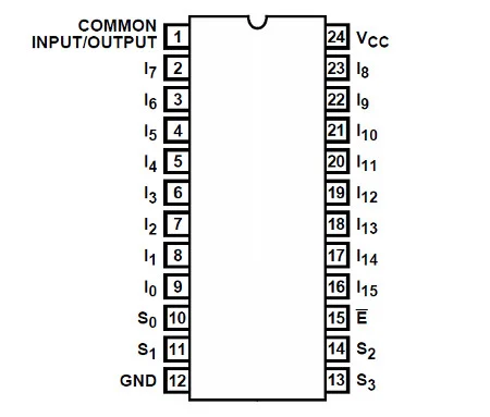
A 4051 or 4067 based analog multiplexer
- Only necessary for the Pi Pico, other microcontrollers have enough analog pins
- Note that for the RB kit without cymbals, you can actually get away with a Pi Pico based board with 4 analog pins, and then the multiplexer is not required.
- 74HC4051 / 74HC4067 recommended, these are
high speedparts and thus they switch faster and work better. - the 74HCT4051 or 74HCT4067 will not work as these are 5V parts and are not tolerant of the 3.3V voltage levels of the Pi Pico.
- The CD4051B/CD4051BE and CD4067B aren't recommended as they are slower parts
- However if you do get one of these, make sure to go for the slow multiplexer option when configuring, otherwise you will end up with drums reading inputs across multiple channels.
-
3.3V zener diode per drum / cymbal pad (if using a multiplexer)
- The multiplexers do not like high voltage spikes, and the zener diode will clamp them. Without this, you will get very messy readings when a drum is hit.
-
1MOhm resistor per drum / cymbal pad
-
Some Wire
-
Soldering Iron
-
Multimeter (it will be used mainly in continuity mode, where it beeps when the two contacts are shorted together)
-
Wire Strippers
-
Wire Cutters
-
Heatshrink
-
Supplies for specific features
- Drum kit from scratch
- 1 Piezo sensor per drum pad / cymbal
- USB Host
- Pi Pico
- One of the following
- A USB female breakout
- A USB extension cable
- A controller with a cable already attached that you are willing to cut
- Drum kit from scratch
Close the tool if you want to use your drum kit, the multiplexer is overridden by the tool when it updates its sensor values, and this will override the controller inputs when it happens.
Wiring Steps
Electronics basics
This guide assumes that you know how to solder, if you do not stop now and go practice soldering.
If you have no idea what a microcontroller is, start here. If you are familiar with microcontrollers and pcbs skip to choosing a microcontroller.
A microcontroller is a small board that can be programmed to perform various functions. In this guide you will be using the microcontroller to replace the main board of the guitar. Around the edge of the microcontroller, you will see various solder through holes called pins. These are labelled with a pinout (which you can find by googling {your microcontroller} pinout) and sometimes on the microcontroller itself. The pins have various functions, but for this controller mod you will need to be familiar with 4 kinds:
- GND (ground) - the common connection that all electrical components must connect to in one way or another in order to complete the circuit. Every set of functions for the guitar will feature a GND pin. On the Pi Pico, you will also see a AGND pin. This is also functionally just another GND, however it is recommended to use this for analog inputs like a stick or whammy.
- VCC (common collector voltage) - this is where you would connect to provide power to a circuit. Sometimes this pin is labelled as 5V, 3.3V or 3v3 on the microcontroller or pinout.
- Digital Pins - These pins are the "basic" pins. They can essentially only show if a button is pressed or not pressed. You will use these for strum, start/select and frets. The are the most common pin on your microcontroller and are usually labelled with just a number.
- Analogue Pins - These pins provide a range of values rather than just on and off. These are the pins you will need to use for whammy, tilt (when using an accelerometer), or your joystick. Analogue pins are labeled on the pinout with A followed by a number.
Analogue pins can be used as a digital pin, but digital pins CANNOT be used as an analogue pin. So if it the instructions say connect to a digital pin, you can use an analogue pin.
Analogue pins can be used as a digital pin, but digital pins CANNOT be used as an analogue pin. So if it the instructions say connect to a digital pin, you can use an analogue pin. V<sub>CC</sub> and GND can have more than one wire soldered to them. For example, if you want tilt and whammy but only have one V<sub>CC</sub> you can solder them both to the single V<sub>CC</sub> pin on the microcontroller.
V<sub>CC</sub> and GND can have more than one wire soldered to them. For example, if you want tilt and whammy but only have one V<sub>CC</sub> you can solder them both to the single V<sub>CC</sub> pin on the microcontroller. Avoid pins 0 and 1 on the Arduino Uno, as these get used for sending controller information over USB.
Avoid pins 0 and 1 on the Arduino Uno, as these get used for sending controller information over USB. Note that on the pi pico you need to use the 3v3 out pin (pin 36) for your V<sub>CC</sub>, not 5V or 3v3_en. The pins on the pico are not rated for 5v, and the 3v3_en pin is actually an input that will stop your pico from starting.
If you are unfamiliar with microcontrollers, you may also be unfamiliar with PCBs in general and figuring out which pins correlate to which function. Here are some terms you will need to know.
- PCB (printed circuit board) - the often green or brown boards containing traces and electronic components
- traces - the copper conductors on a board. They look flat and are often metalic. Think of them as "wires" on the board itself connecting components. If you are still confused, a quick google can help you understand traces.
To keep the relevant information in this guide easy to find, information is sorted by function.
Face buttons
- Trace the pads on the drum PCB that contains the face buttons. The face buttons should have a common ground, you should see this as a trace that connects multiple buttons together. Find some way to connect a wire to this, if there is a test pad or something you can solder to, solder your wire to that, otherwise you will need to scrape back one of the traces with a knife so you can solder to that. Solder this to ground on your microcontroller.
- Follow the traces for the other side of each button, and solder a wire to them in a similar way as the common wire. Then solder that to a digital pin on your microcontroller.
Multiplexer
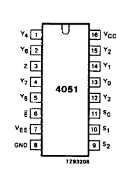
- Wire V<subCC on the multiplexer to 3v3 on the Pico.
- Wire VSS to GND on your Pico
- If your multiplexer has a VEE, also wire that to ground on the Pi Pico. VEE allows for using the multiplexer with negative voltages, but since we aren't doing this we set it to ground to disable that feature.
- Also wire INH / Inhibit to ground, if this exists on your multiplexer. This pin disables the I/O if it is driven high, so we ground it to make sure the chip is always enabled.
- Wire the analog output (Often labelled COM or common in/out, but also labelled SIG on some breakout boards) on the multiplexer to an analog pin on your Pi Pico.
- Wire A/S0, B/S1 and C/S2 (and D/S3 for the 16 channel multiplexer) to seperate digital pins on your Pi Pico.
- Wire each drum pad to a different channel on the multiplexer.
Drum / Cymbal pads
Note that the piezo is directional and does need to be wired in the correct way. If it doesn’t work, swap the wires around.
- Disconnect the piezos from the main drum PCB.
- Solder the black wire from the piezo to ground.
- Solder the red wire to an analog input on the multiplexer / micocontroller.
- Solder a 1Mohm resistor between the analog input your piezo is connected to on your multiplexer / microcontroller and ground
- Solder a diode between the analog input your piezo is connected to on your multiplexer / microcontroller and ground
RB Pedal
- The pedal connector has two wires coming out of it. Connect one to ground and one to a digital pin on your microcontroller.
GH Pedal
- Solder the one wire from the pedal connector to ground.
- Solder the other wire to an analog input on the multiplexer for the Pi Pico, or to an analog pin on your micocontroller if your microcontroller has enough analog pins.
- Solder a 1Mohm resistor between the two wires on the pedal connector.
USB Host (Pi Pico Only)
If you want to use your controller on an unmodifed Xbox 360 or Xbox One or Xbox Series, you can connect a USB port to the Pi Pico.
- If you are using a USB extension cable, cut it in half and expose the four cables.
- Hook up the V+ / VBUS (Red) to the VBUS pin on your Pi Pico
- Hook up the V- / GND (Black) to ground on your Pi Pico
- Hook up D+ (Green) to a unused digital pin.
- Hook up D- (White) to the digital pin directly after D+. For example, you can hook up D+ to GP2 and D- to GP3.
Programming
-
Start Santroller with your microcontroller plugged in.
-
Set the Input Type to Directly Wired
-
Click on
Configure -
Click on
Controller Settings -
Set
Emulation TypetoControllerfor standard guitars andFortnite Festivalfor Fortnite Festival. -
Set the
Controller Typebased on the game you want to play. -
Windows controller modecan be set based on your preferences. Note that this is only for Windows, no other operating systems or consoles will be affected by this option.XInput- This works more natively on windows, and most games will automatically bind controls.HID- This uses HID on windows, which means games won't automatically bind controls, but HID is polled a bit more efficiently in games like Clone Hero.
-
If you would like to adjust settings related to polling, click on
Controller Poll Settings -
Set the Poll Rate to your preferred setting. 0 sends data as fast as possible, any other number polls inputs at that speed.
-
Debounce can be adjusted here. You will need to increase this, as debounce sets the minimum time for a drum hit, and this will turn the drum hit that only occurs for a few microseconds into a signal that the game expects. While testing I used a debounce of 20ms but you will have to adjust this to find a value that works for you. The main thing to consider is that it takes a bit of time between you going to hit a drum pad and you hitting the pad, so if the debounce is too low, you may just miss drum hits due to the note not being on for long enough.
-
Now you can start setting up your inputs. To keep this information relevant, it is grouped by function.
Face buttons / RB Pedal
- Click on the button you want to configure, and make sure the
Input Typeis set toDigital Pin Input. - Make sure
Pin Modeis set toPull Up. - Click on the
Find Pinbutton, and then press the button on the guitar. If you have wired everything correctly, the tool should detect the pin and the icon for that button should now light up whenever the button is pressed.
Drum / Cymbal pads / GH Pedal (Multiplexer)
- Click on the drum pad in question
- Set the
Input Typeto multiplexer - Set the S0, S1, S2 (and S3 for a 4067 based multiplexer) pins
- Set the analog output / SIG / COM pin to the analog pin you wired it to
- Hit the drum pad in question. You should see the raw value for the drum pad change.
- Hit the pad lightly, and drag the minimum up so that it registers small hits.
- Hit nearby pads and make sure that the vibrations from those pads don't activate the pad you are configuring. If they do, then increase the minimum. You should end up with each pad registering hits, without crosstalk or needing to hit the pads too hard.
Drum / Cymbal pads / GH Pedal (Direct analog)
- Click on the drum pad in question
- Set the
input typetoAnalog Pin Input - Click on
Find Pinand then hit the drum pad in question, it should detect the drum that was just hit. - Hit the drum pad in question. You should see the raw value for the drum pad change.
- Hit the pad lightly, and drag the minimum up so that it registers small hits.
- Hit nearby pads and make sure that the vibrations from those pads don't activate the pad you are configuring. If they do, then increase the minimum. You should end up with each pad registering hits, without crosstalk or needing to hit the pads too hard.
USB Host (Pi Pico Only)
- Click on Add setting
- Find and add
USB Host inputs - Bind D+
- Hit Save
- If you plug in a supported controller, the tool should detect it and tell you what it is.
- If you have a modded xbox and are using
usbdsecpatch, you can disableAuthentication for Xbox 360.
- Click on the button you want to configure, and make sure the