Setting up an Adaptor for a Wii Controller
Supplies
-
A microcontroller
-
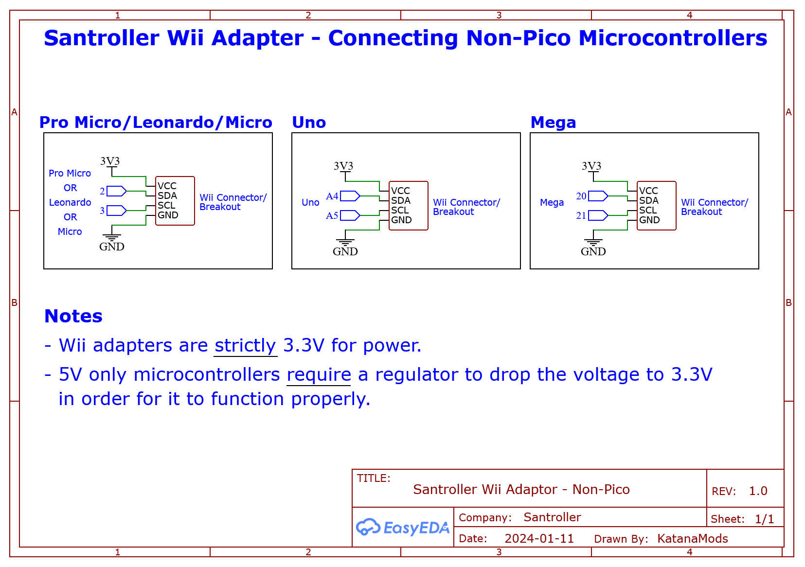
The Pi Pico is recommended, but click below to see information about other microcontrollers.
Microcontroller information
- Pi Pico
- This micro controller was created by the Raspberry Pi foundation, so it means that buying one supports them instead of random companies cloning Arduinos. They are considerably more powerful than any of the other supported Arduinos. The Pi Pico supports a few extra features, such as USB Input (which allows for XB1 / Series compatability), Peripheral microcontrollers and the GHWT tap bar. Note that the Pi Pico runs at 3.3v, so it can just be used as is for PS2 and Wii adapters. Pi Picos also tend to be quite cheap and often have the advantage that they can often be brought at local stores. With the currrent firmware, picos work much much better than arduinos if your goal is to create adaptors, but they also work better for direct wiring too. There are many boards based on the Pi Pico as well, and all of these work just fine with the firmware.
- Sparkfun Pro Micro (5v)
- The 5V Pro Micro will work okay for direct wiring, but being that it runs at 5V, it will require voltage conversion to build Wii adapters and PS2 adapters and turntables.
- Sparkfun Pro Micro (3.3v)
- If you want to build an adapter for a Wii or PS2 guitar, then this will be easier to use than any of the 5v microcontrollers. Due to the lower voltage, these do run at half the speed of the 5v variants, a. Clones of the Pro Micro are quite cheap but will need to be purchased from ebay or aliexpress, real Pro Micros are quite expensive but there isn't really much of a difference. 3.3V arduinos will poll a wii guitar slightly slower than a 5V arduino but in practise this does not end up mattering as there are a lot of other delays necessary for communicating with a wii guitar.
- Arduino Micro
- This is essentially the same thing as a 5v Pro Micro, however these are officially made by Arduino. These are often a bit more expensive as they aren't really cloned.
- Arduino Leonardo
- This is essentially a 5v Pro Micro with the layout of a Arduino Uno, so you get more pins but it is also much larger. You can get clones of these, but they are still more expensive than Pro Micros or picos.
- Arduino Uno (r1/r2/r3)
- These micro controllers are actually two micro controllers in one, and they work in tandem to provide a working controller. This has its disadvantages, as code needs to keep these controllers in sync, and this can result in issues if a bad configuration is programmed, and generally results in requiring more complicated and optimised code to work. Unos do still get 1000hz, but I would recommend against them if you are buying a new Arduino. Note that some clone Arduino Unos are actually missing the second micro controller, and these ones will NOT work at all. If you see an Arduino Uno listing that mentions "ch340g" or something along those lines do not purchase it. Due to this, they are harder to purchase and since they require more parts, they are more expensive than a Pro Micro or Pi Pico.
- Arduino Mega 2560
- These are in the same situation as the Uno, however the main micro controller has a lot more pins. These do also end up being rather expensive due to the sheer amount of parts that are needed to make one.
- Arduino Uno r4
- This is the newest entrant to the Arduino Uno line, and it is a totally different microcontroller and hence it is not supported.
- Arduino Mini or Nano or Pro Mini or Pro Nano
- These do NOT work, as they are essentially Unos that lack the second micro controller that allow for custom USB device emulation.
- ESP32
- Currently this is not supported due to the base ESP32 not fully supporting USB. There are some ESP32 models that have USB support, but these end up being more expensive than the Pi Pico, and thus it does not make sense to support these.
- Pi Pico
-
-
A Wii extension breakout board or an extension cable, such as
. You can also choose to cut the end of the extension and solder your own cables on as well if you perfer.
-
If your wii extension breakout does not support 3.3v input, and you are using a 5v Pro Micro, you will need a 3.3v voltage regulator. The breakout listed above does however support either voltage so this is not required for that breakout.
-
Some Wire
-
A Soldering Iron
-
Supplies for specific features
- Tilt
- Any of the following options are supported
- A Digital Tilt Switch (somtimes called a mercury or ball tilt switch)
- I recommend using two tilt sensors in series, as this can help with accidental activations
- The ADXL345, MPU-6050 or LIS3DH Accelerometer
- This gives a proper analog value of the devices acceleration
- Tilt is detected by observing acceleration due to gravity
- This gives a proper analog value of the devices acceleration
- An analog accelerometer, such as the ADXL335, or the accelerometer on some GH guitars
- This gives a proper analog value of the devices acceleration
- Tilt is detected by observing acceleration due to gravity
- This gives a proper analog value of the devices acceleration
- A Digital Tilt Switch (somtimes called a mercury or ball tilt switch)
- Any of the following options are supported
- Tilt
Be careful that you don’t ever provide 5v power to the power pin of a Wii Extension, as they are not designed for this. The data pins however are tolerant of 5v, so you can hook these up directly to pins on your microcontroller.
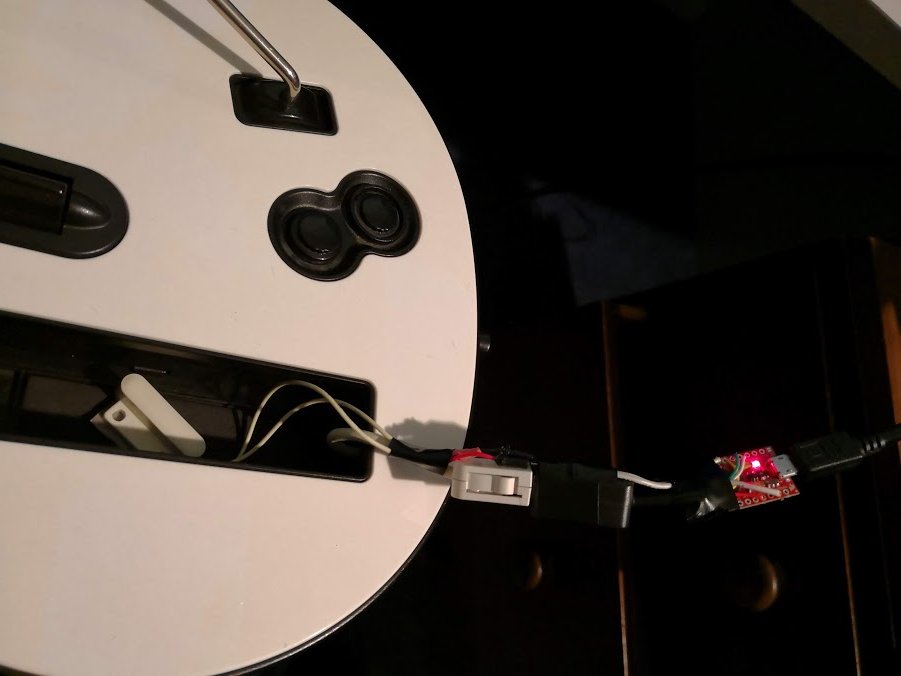
The finished product
Steps
-
Connect wires between the SDA and SCL pins on your breakout board / wii extension cable. Refer to the following image for the pinout of a Wii Extension connector.
The Pi Pico lets you pick from various pins for the SDA and SCL pins. We provide recommended pins below, and this pinout is the same as the old Ardwiino firmware. If you need to use other pins, the options are provided below but the SDA and SCL pins must be from the same channel.
 Danger
If you are using a wii extension cable do NOT rely on the colours, the manufacturers are all over the place with this and the only way to validate them is to test each wire according to the above image. I’ve come across connectors wired with green as ground and black as 3.3V before, you just can’t rely on the colours at all unfortunately.
Microcontroller SDA SCL Pi Pico (Recommended) GP18 GP19 Pro Micro, Leonardo, Micro 2 3 Uno A4 A5 Mega 20 21 Pi Pico (Advanced, Channel 0) GP0, GP4, GP8, GP12, GP16, GP20 GP1, GP5, GP9, GP13, GP17, GP21 Pi Pico (Advanced, Channel 1) GP2, GP6, GP10, GP14, GP18, GP26 GP3, GP7, GP11, GP15, GP19, GP27 -
Connect the VCC on the microcontroller to the VCC on the breakout
- If you are using a 5v Pro Micro, and your breakout does not support 5v input, then you will need to hook up VCC from the microcontroller to a 3.3v regulator, and then hook up the output of the regulator to the breakout
- If you are using the microcontroller uno, use the 3.3v pin on your microcontroller as VCC
- If you are using the breakout linked
vinpin is used for both 3.3v input and 5v input. The 3v pin is actually an output and is not needed for this project.
-
Connect the gnd pin on the wii breakout / extension cable to the gnd on your microcontroller.
-
If you would like to use tilt:
Digital Tilt
- Connect one pin of the first tilt sensor to ground
- Connect the other pin of the first tilt sensor to a pin on the second tilt sensor
- Connect the other pin of the second tilt sensor to a digital pin on your microcontroller.
- Affix the sensors to your guitar. You will need to play around with their position to get them to activate at the exact point you want tilt activating.
Analog Tilt
- Connect GND to GND
- Connect VCC to VCC
- Connect the signal pin to an analog pin on your microcontroller
ADXL345 Or MPU 6050 or LIS3DH
- Connect GND to GND
- Connect VCC to VCC (note that this is a 3.3v device, so for 5V microcontrollers make sure your breakout has a voltage regulator onboard or you are using your own regulator)
- Hook up SDA and SCL to the microcontroller
Microcontroller SDA SCL Pi Pico (Recommended) GP18 GP19 Pro Micro, Leonardo, Micro 2 3 Uno A4 A5 Mega 20 21 Pi Pico (Advanced, Channel 0) GP0, GP4, GP8, GP12, GP16, GP20 GP1, GP5, GP9, GP13, GP17, GP21 Pi Pico (Advanced, Channel 1) GP2, GP6, GP10, GP14, GP18, GP26 GP3, GP7, GP11, GP15, GP19, GP27
Programming
-
Start Santroller with your microcontroller plugged in.
-
Set the
Connection MethodtoWii Adapter. -
Set
Device to Emulatefor the type of device you want to emulate. -
For guitars, if you wish to add tilt,
-
Hit Configure
-
If you are on the Pi Pico and are using different pins, set your SCL and SDA pin.
-
Hit
Save Settings. -
Windows controller modecan be set based on your preferences. Note that this only affects windows, a controller in XInput mode will use the correct mode on a console, and will automatically use HID mode on Linux and macOS.XInput- This works more natively on windows, and most games will automatically bind controls.HID- This uses HID on windows, which means games won't automatically bind controls, but HID is polled a bit more efficiently in games like Clone Hero.
-
If you would like to adjust settings related to polling, click on
Controller Poll Settings -
If you would like to use
Queue Based Inputsyou can turn that on here. This puts any buttons you press into a queue, and sends them out to the PC as fast as USB allows. This means that the controller will process your inputs at a faster poll rate than 1ms (the fastest rate USB allows) and then the PC will be sent your inputs at a 1ms rate. -
Set the Poll Rate to your preferred setting. 0 sends data as fast as possible, any other number polls inputs at that speed.
- Note that for
Dj Hero Turntablesthis needs to be set to 10, otherwise the platter won't work correctly.
- Note that for
-
Debounce can be adjusted here. Debounce is necessary as button inputs are noisy. When you hit a button, it will often bounce and send multiple presses, which some games may percieve as you hitting the button multiple times, which can result in dropped sustains. When you set debounce to a value, the signal ignores any release inputs for that time frame, so if you for example set it to 1ms, then the button input will be on for a minimum of 1ms, and only after that will the release be processed. This has the effect of stretching out the button press to at least 1ms, which ignores any bouncing in that timeframe.
-
Combined strum debounce shares the debounce timeframe between both strums (only available on guitars). This means that if you set the strum debounce to 1ms and strummed down, both strum up and down inputs are ignored over that 1ms timeframe. This helps avoid extra strum inputs when your strum switch rebounds after being released.
-
Click on
Wii Extension Inputs -
If you are using a Pi Pico, specify the SDA and SCL pins that you wired your extension port to.
-
Hit Save.
-
You can now calibrate your inputs. If your controller is already plugged in it should be detected and show only those inputs, but you can use the
Wii Inputs to display belowdropdown to specify the controller you want to configure.- Joysticks or crossfader
- Hit the
Calibratebutton and then move the stick all the way left / up - Hit
Nextand then move the stick all the way right / down - Hit
Nextand then move stick a little bit away from the center. This sets the deadzone, and any inputs closer to the center from this position will be ignored, which helps with noisy sticks.
- Hit the
- Whammy
- Click on
Calibrate. - Release the whammy bar and hit
Next. - Push the whammy all the way in, and hit
Next - Release the whammy again, and hit
Next. If your whammy is noisy, you can push it in a tiny bit, and the zero position will be set to this location, which will make sure that the whammy is always considered released when it is released.
- Click on
- Turntable Spin
- If your turntable isn't responsive enough in games, you can set a multiplier, which will multiply the value coming from the table by a constant amount.
- Joysticks or crossfader
-
If you would like to use Tilt, make sure you are emulating a guitar, and then hit
Add Settingand add aTiltsetting. Then follow one of the below options:Digital Tilt
- Click on Tilt, and make sure the
Input Typeis set toDigital Pin Input. - Make sure
Pin Modeis set toPull Up. - Click on the
Find Pinbutton, and then tilt your guitar. If you have wired everything correctly, the tool should detect the pin and the tilt icon should light up whenever you tilt the guitar. - If you are using a SW520D based tilt sensor, some versions of this sensor will have an inverted output. You can turn on the
Invertoption to correct this.
Analog Tilt
- Click on Tilt, and make sure the
Input Typeis set toAnalog Pin Input. - Click on the
Find Pinbutton, and tthen tilt your guitar. If you have wired everything correctly, the tool should detect the pin and the tiltOriginal Valuevalue should change as you tilt your guitar. - Click on
Calibrate - Tilt your guitar down, and then hit
Next - Tilt the guitar up, and then hit
Next - Hold your guitar in its resting position and then hit
Next.
ADXL345 or MPU-6050 or LIS3DH based Tilt
- Click on
Add setting - Add an
Accelerometer - For the Pi Pico, set the SDA and SCL pins that you have used.
- Set the
Accelerometer Typefor your given sensor - Hit save.
- Click on Tilt, and make sure the
Input Typeis set toAccelerometer Input. - Click on
Calibrate - Hold your guitar in its resting position, and then hit
Next - Tilt the guitar up, and then hit
Next - Tilt your guitar up a little bit and then hit
Next. Values below this position will be zeroed. With the adxl, you can increase the deadzone to help counteract strumming or shaking activating tilt. - Adjust the
Low Pass Filter. This value controls how new value from the ADXL are filtered, a value closer to 0 will result in a sensor that won't respond to a shake or strumming, but if you decrease it too much the sensor will have a decreased responsiveness. If you set it closer to 1, then the sensor will be very responsive but it will also pick up any tiny vibrations as well. From testing a value of 0.05 seemed like a good place to start.
- Click on Tilt, and make sure the